Steel Building Shop Drawing Review in Canada: What Must Be Resolved Before Fabrication
A steel building shop drawing review checks whether the current fabrication and detailing information is consistent with the defined structural design intent, project documents, engineering responsibilities and critical interfaces before fabrication is released.
That review matters because a steel building problem can begin long before the material reaches the site.
A base plate is detailed for an outdated anchor pattern.
An overhead-door header conflicts with the required clear opening.
A connection is shown without adequate bolt edge distance.
A roof opening appears on the mechanical drawings but not on the steel package.
A framed opening moves after the wall girts have already been fabricated.
A detailer uses an architectural dimension while the foundation drawings use a different structural grid.
These problems do not always begin with an incorrect structural calculation.
They often begin when design information is:
- incomplete
- inconsistent
- outdated
- misunderstood
- translated incorrectly into fabrication instructions
- revised without being carried through the complete drawing and model package
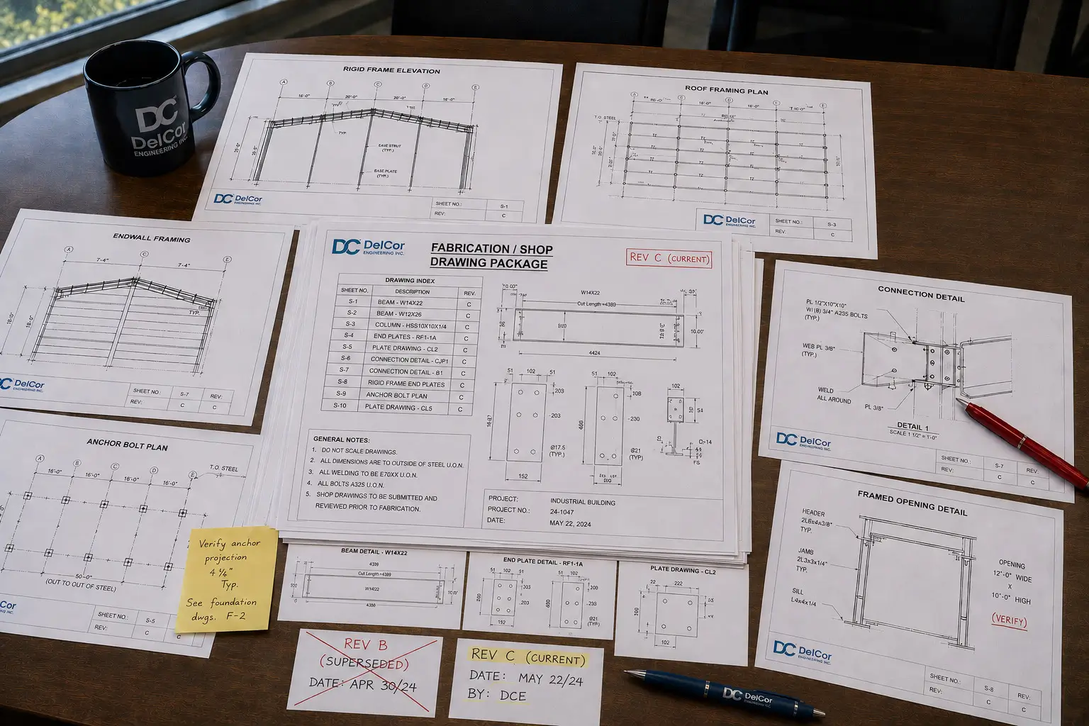
Shop drawings sit at the point where coordinated engineering information becomes fabricated steel.
They are used to communicate how members and assemblies will be:
- cut
- drilled
- welded
- bolted
- marked
- assembled
- packaged
- shipped
- located during erection
The critical question is not only:
“Were the shop drawings reviewed?”
It is:
“Do the current shop drawings accurately translate the coordinated design into fabricable and erectable steel, and has the project team resolved the conditions that control fabrication release?”
Quick Answer
Steel building shop drawing review evaluates the submitted fabrication information against the defined structural design basis and project requirements within the reviewer’s confirmed scope.
Depending on the project, the review may consider:
- member sizes and material grades
- building geometry
- connection arrangements
- plates and stiffeners
- bolts and welds
- bracing
- base plates and anchors
- framed openings
- roof openings
- foundation interfaces
- delegated-design content
- cladding-support interfaces
- drawing revisions
- model revisions
- review comments
- fabrication-release conditions
A shop drawing review is not automatically:
- detailed checking of every dimension
- quantity verification
- material takeoff
- fabrication quality control
- field measurement
- connection design
- erection planning
- temporary-bracing design
- authorization to ignore unresolved comments
- acceptance of superseded project information
The review purpose, status, limitations and responsibility boundaries should be established through the project documents and written professional scope.
Shop Drawings Translate Design Into Fabrication
Structural design documents establish what the completed building must achieve.
Shop drawings communicate how individual steel members and assemblies are to be manufactured and identified.
The structural documents may establish:
- structural grid
- building geometry
- member sizes
- design loads
- bracing locations
- foundation reactions
- connection forces
- connection restrictions
- material requirements
- performance criteria
- design assumptions
The shop drawings may then establish:
- exact member lengths
- plate sizes
- hole patterns
- cuts and copes
- weld locations
- bolt arrangements
- piece marks
- assembly marks
- fabrication notes
- shipping units
- erection references
A structurally correct design can still be fabricated incorrectly when this translation is incomplete.
A precise fabrication drawing can also be wrong if it was developed from outdated structural, architectural, supplier or foundation information.
Shop drawing quality therefore depends on both:
- the quality and completeness of the engineering information
- disciplined coordination, review and revision control
Steel Project Documents Serve Different Purposes
The broader differences between supplier drawings, engineering drawings and permit drawings should be established in the project’s drawing-scope documents.
For shop drawing review, the important distinction is whether each document provides design requirements, fabrication information, erection information or interface information.
| Document Type | Primary Purpose |
| Structural design drawings | Communicate structural design intent, member requirements, loads, dimensions and interfaces within the engineer’s scope |
| Permit drawings | Support the permit submission using the project information required by the authority having jurisdiction |
| Supplier or manufacturer drawings | Describe the supplied building system, geometry, components, reactions, openings and scope |
| Approval or confirmation drawings | Allow selected geometry, openings and interfaces to be confirmed before detailed fabrication proceeds |
| Shop or fabrication drawings | Provide detailed information used to manufacture individual steel pieces and assemblies |
| Erection drawings | Show the location, orientation and identification of fabricated components for field assembly |
| Anchor-interface information | Communicate column positions, base plates, anchors, reactions and steel-to-foundation requirements |
| Connection calculations | Demonstrate delegated or specialty connection engineering where required |
| Record or as-built information | Document completed work according to the defined contractual and professional process |
The exact titles and boundaries vary.
The project documents should define:
- who prepares each document
- who is responsible for its technical content
- who reviews it
- what the review means
- which revision is current
- when fabrication may proceed
- which document governs when information conflicts
A drawing title alone does not establish authority, completeness or responsibility.
Approval Drawings Are Not Automatically Fabrication Drawings
Some manufacturers and suppliers issue approval or confirmation drawings before detailed shop drawings are completed.
These may be used to confirm:
- building width and length
- eave height
- roof slope
- bay spacing
- frame locations
- door openings
- framed openings
- canopies
- lean-tos
- column reactions
- base plate geometry
- cladding selections
This stage can provide a valuable hold point.
However, an approval drawing is not automatically:
- a complete fabrication drawing
- a final connection detail
- a permit-ready document
- a construction-layout drawing
- confirmation of field dimensions
- final foundation information
- authorization to fabricate
The project team should read the drawing issue status and transmittal carefully.
Terms such as:
- preliminary
- for review
- for confirmation
- for permit
- for construction
- released for fabrication
- superseded
represent materially different document states.
Information That Must Be Resolved Before Detailed Fabrication
A detailer can prepare reliable shop drawings only from coordinated inputs.
Building Geometry
Confirm:
- structural grid
- building width and length
- eave and ridge heights
- roof slope
- bay spacing
- frame spacing
- wall steps
- roof steps
- canopies
- lean-tos
- mezzanines
- attached structures
Openings
Confirm:
- overhead-door sizes
- hangar-door sizes
- personnel doors
- windows
- louvres
- vents
- roof openings
- service penetrations
- loading-dock openings
Structural Information
Confirm the current:
- structural drawings
- member sizes
- design loads
- connection forces or criteria
- bracing locations
- diaphragm requirements
- deflection limits
- reactions
- material requirements
- project specifications
Critical Interfaces
Confirm:
- foundation grid
- anchor arrangement
- base plate geometry
- slab elevation
- finished-floor elevation
- concrete-curb interfaces
- masonry or precast interfaces
- door-system requirements
- equipment supports
- stairs
- railings
- cranes
- suspended loads
Project Controls
Confirm:
- current drawing register
- revision history
- current model version
- RFI log
- substitution log
- approved changes
- submission sequence
- review responsibility
- fabrication-release process
Unresolved information should remain visible as an open item.
It should not be converted quietly into a detailing assumption.
Detailers Should Not Be Forced to Design by Guesswork
Steel detailers make many technical decisions as part of normal detailing practice.
They should not be expected to invent missing structural design requirements.
Potentially unsafe assumptions include:
- selecting a connection force without criteria
- moving bracing to avoid a door
- changing a member size
- reducing plate thickness
- relocating anchors
- enlarging holes
- cutting a structural flange
- omitting a stiffener
- adding an unapproved field weld
- changing a bolt grade
- assuming roof sheeting acts as a diaphragm
- assigning an unverified field dimension
- deciding that a structural component is unnecessary
When the documents do not provide enough information, the issue should be raised through the project’s formal clarification process.
A documented RFI is safer than an undocumented engineering assumption embedded in a fabrication model.
Connection Responsibility Must Be Defined Before Review
Connection design is one of the most important responsibility boundaries in structural steel work.
Several project arrangements are possible.
Connections Designed by the Project Structural Engineer
The structural drawings may provide complete connection:
- geometry
- plate sizes
- bolt requirements
- weld requirements
- stiffeners
- material requirements
The fabricator then details those requirements for fabrication.
The review may confirm that the submitted detailing follows the design information.
Connections Delegated to a Specialty Engineer
The structural documents may instead provide:
- connection forces
- design criteria
- load combinations
- permitted connection types
- geometric restrictions
- material requirements
- required stiffness or ductility
- interface conditions
A specialty engineer then designs and authenticates the connection engineering within the delegated scope.
The calculations, drawings and review process should make the responsibility boundary clear.
Fabricator-Selected Connections Under Defined Criteria
Some projects allow the fabricator to select standard connections using established criteria.
The contract documents should still define:
- permitted connection families
- design forces
- restrictions
- applicable standards
- calculation requirements
- review requirements
- authentication requirements where engineering is involved
The project should not reach detailed fabrication with each party assuming someone else is responsible for connection design.
Professional Authentication and Shop Drawing Review Are Different Acts
Professional authentication identifies responsibility for engineering content within a defined document and scope.
A shop drawing review notation communicates that a separate review has occurred for the purpose stated in the contract, review procedure and notation.
These acts should not be treated as interchangeable.
Where shop drawings contain project-specific engineering design, the professional responsible for that engineering must authenticate the applicable documents according to the requirements of the project jurisdiction.
Examples may include:
- delegated connection design
- proprietary structural components
- specialty trusses
- stairs
- guards
- equipment supports
- cold-formed steel framing
- cladding-support systems
- temporary works
A reviewing engineer who is not assuming responsibility for that engineering content should not use a professional seal in a way that implies otherwise.
A separate shop drawing review notation should identify:
- the purpose of the review
- the limitations of the review
- the review status
- whether comments must be incorporated
- whether resubmission is required
- whether fabrication may proceed
Professional authentication, shop drawing review and fabrication release may be performed by different parties and may represent different project decisions.
Requirements vary by province and territory.
The applicable engineering regulator, contract documents and confirmed professional scope govern the actual project.
Ontario Guidance Is Not Automatically National Guidance
Professional Engineers Ontario regulates professional engineering practice in Ontario.
PEO guidance can help explain Ontario practice regarding engineering responsibility, authentication and general-conformance review.
It should not be treated as the national regulator for Canada.
Other provinces and territories have their own:
- engineering legislation
- regulators
- authentication requirements
- professional-practice guidance
- terminology
- electronic-document requirements
One regulator’s stamp, seal or review wording should not be copied into another jurisdiction without verification.
The project team should confirm the requirements of the regulator governing the professional work for the actual project.
Shop Drawing Review Is Not Independent Re-Design
Shop drawing review is often misunderstood.
An owner may assume the reviewer checks every number.
A fabricator may assume review transfers responsibility.
A contractor may interpret a review mark as permission to fabricate despite unresolved comments.
Those assumptions are risky.
Depending on the written scope, the review commonly considers whether the submission is generally consistent with:
- structural design intent
- current contract drawings
- project specifications
- identified design criteria
- connection-responsibility boundaries
- critical interfaces
- accepted project changes
It does not normally mean the reviewer independently verifies every:
- fabrication dimension
- quantity
- piece mark
- cutting length
- field measurement
- material order
- shop procedure
- welding sequence
- erection method
- temporary condition
- contractor safety measure
The precise review purpose and limitation should be stated in the agreement and review notation.
The Contractor and Fabricator Should Review Before Submission
A consultant review should not be the first quality-control check.
Before submission, the contractor, manufacturer, detailer and fabricator should review matters within their responsibility, which may include:
- field dimensions
- quantities
- fabrication feasibility
- material availability
- piece identification
- project geometry
- door and equipment coordination
- transport restrictions
- erection clearances
- coating requirements
- architectural coordination
- mechanical and electrical openings
- connection access
- completeness
- current revision status
Submitting incomplete or knowingly uncoordinated drawings increases:
- review cycles
- schedule pressure
- comment volume
- fabrication risk
- the chance that a significant issue is hidden among avoidable drafting corrections
Review Status Must Be Defined
Projects use different shop drawing status terms.
Examples include:
- reviewed
- reviewed as noted
- revise and resubmit
- rejected
- no exceptions taken
- reviewed for general conformance
These terms do not have one universal legal or contractual meaning.
The project procedure should define:
- what each status means
- whether fabrication may proceed
- whether comments must be incorporated
- whether a revised drawing must be resubmitted
- who controls final release
The word approved should be used cautiously.
A broad approval stamp may imply more checking or responsibility than the reviewer intended.
“Reviewed as Noted” Does Not Mean Comments Are Optional
Review comments may identify:
- drafting corrections
- dimensional conflicts
- structural revisions
- missing information
- unresolved interfaces
- required calculations
- conflicts with another discipline
A comment on one detail may affect:
- adjacent members
- bolt lists
- erection drawings
- anchor details
- foundation interfaces
- material orders
- related assemblies
- the fabrication model
Comments should be incorporated systematically into the source model and revised documents.
They should not exist only as handwritten notes on one PDF.
Fabrication Release Must Be Controlled Separately
A reviewed drawing is one input to fabrication release.
Before material is cut, the responsible project parties should confirm that:
- the review status permits fabrication
- required comments are incorporated
- the current revision is identified
- connection engineering is complete
- calculations are submitted where required
- door and roof openings are confirmed
- foundation and anchor information is coordinated
- accepted substitutions are incorporated
- outstanding RFIs are resolved or expressly excluded
- material grades and coatings are confirmed
- no later design revision supersedes the package
Fabrication release should be documented.
An informal verbal direction can be difficult to reconstruct after steel has been ordered or fabricated.
Anchor Rods and Base Plates Are Critical Interfaces
Shop drawings often connect the steel package to the foundation through:
- column locations
- base plates
- anchor rods
- anchor templates
- grout space
- shear-transfer details
- edge distances
- concrete pedestals
- foundation reactions
The project team should confirm:
- structural grid
- column orientation
- base plate dimensions
- anchor diameter
- anchor spacing
- anchor projection
- hole size
- slot direction where permitted
- grout thickness
- pedestal dimensions
- concrete edge distance
- setting tolerances
- current reaction revision
Shop drawings should not silently override the foundation design.
Anchor Plans Are Not Complete Foundation Drawings
An anchor plan may communicate the steel supplier’s required anchor geometry.
It may not include:
- footing design
- concrete reinforcement
- anchor embedment design
- concrete breakout resistance
- frost requirements
- geotechnical assumptions
- survey responsibility
- construction-layout requirements
A base plate and anchor pattern can fit the steel column while remaining incompatible with:
- concrete geometry
- reinforcement
- footing design
- foundation tolerances
- edge-distance requirements
The foundation, steel and construction-layout documents must be coordinated before concrete is placed.
Large Openings Create Fabrication and Review Risk
Large doors affect more than wall cladding.
They can alter:
- columns
- jambs
- headers
- girts
- bracing
- flange restraints
- frame reactions
- cladding support
- erection sequencing
- door tolerances
Before fabrication, confirm:
- clear opening
- rough opening
- door-manufacturer requirements
- jamb reactions
- header loads
- track clearance
- operator clearance
- weather-seal space
- finished-floor elevation
- exterior apron elevation
- structural deflection limits
A nominal door size does not necessarily equal the required structural opening.
The selected door system should be coordinated with the steel framing before the jambs, headers and girts are fabricated.
Roof Openings Must Be Resolved Before Purlin Fabrication
Roof openings may be required for:
- HVAC units
- exhaust fans
- roof hatches
- skylights
- smoke vents
- ducts
- piping
- process equipment
- solar equipment
Confirm:
- opening size
- curb size
- equipment weight
- support reactions
- purlin interruption
- framed-opening members
- drainage
- snow accumulation
- cladding support
- maintenance access
- replacement clearances
Cutting a purlin in the field because an opening was missed can interrupt the intended load path.
A coordinated framed opening is normally safer and more economical than an emergency reinforcement detail developed after fabrication.
Mezzanines, Cranes and Suspended Loads Need Early Input
Steel buildings frequently receive internal systems after the base building has been quoted.
Examples include:
- mezzanines
- cranes
- hoists
- conveyors
- storage platforms
- process equipment
- suspended ceilings
- sprinkler mains
- mechanical services
- racking interfaces
These loads can affect:
- frame members
- connections
- purlins
- girts
- bracing
- base reactions
- foundations
- fabrication details
A note such as “future crane” is not sufficient design information.
The loads, positions, operating characteristics, support points and connection requirements must either be defined before fabrication or clearly excluded from the current building scope.
Metal Sheeting Is Not Automatically a Structural Diaphragm
Where roof or wall cladding forms part of the steel package, the detailing may include:
- panel orientation
- sheet lengths
- sidelaps
- end laps
- fastener patterns
- edge zones
- corner zones
- trims
- closures
- openings
- gutters
- downspouts
- insulation interfaces
Metal roof or wall sheeting should not be assumed to resist structural diaphragm forces unless that role is expressly included in the design.
Where diaphragm action is required, the engineering and shop information should address:
- panel capacity
- support fasteners
- sidelap fasteners
- chords
- collectors
- boundary connections
- openings
- load transfer
Changing panels, fastener spacing or openings in the field can affect the lateral system when cladding forms part of the designed diaphragm.
Integrated Steel Building Systems Use a Different Delivery Model
A conventional structural steel project may involve separate:
- structural engineer
- detailer
- fabricator
- connection engineer
- erector
- cladding supplier
An integrated steel building system may combine primary framing, secondary framing and cladding within a manufacturer-designed package.
For a CSA A660-certified manufacturer, the certified process addresses the manufacturer’s responsibility for the integrated steel building system within its defined scope.
That may include controls relating to:
- structural design
- materials
- fabrication
- quality systems
- shipping
- erection documentation
CSA A660 certification does not automatically cover work outside the manufacturer’s defined system, such as:
- site planning
- foundations
- geotechnical design
- grading
- slab design
- attached structures by others
- mechanical equipment
- contractor installation
- general permit coordination
The shop drawing and review process should match the actual project-delivery model and supplier scope.
BIM Does Not Eliminate Drawing Responsibility
Digital models can improve:
- geometric coordination
- clash detection
- piece identification
- fabrication automation
- quantity control
- erection planning
They also create risk when the project does not define which information is authoritative.
The project should establish:
- whether the model is contractual
- which version is current
- who may edit it
- how external references are updated
- whether drawings or model data govern
- what information may be relied upon
- how review comments are incorporated
- how fabrication release is recorded
A model can appear coordinated while still containing:
- outdated connection forces
- incorrect material grades
- unapproved opening changes
- duplicated parts
- missing fasteners
- superseded geometry
Digital coordination does not replace document control, engineering responsibility or formal release.
Revision Control Is a Fabrication-Safety System
A shop drawing revision process should identify:
- revision number or letter
- revision date
- description of change
- affected pieces
- affected assemblies
- review comments incorporated
- fabrication status
- material already ordered
- material already fabricated
- superseded drawings
A change to one opening may affect:
- girts
- bracing
- columns
- cladding
- reactions
- anchor information
- erection drawings
- adjacent assemblies
Superseded Drawings Must Be Removed
Old information should not remain active:
- on the shop floor
- in fabrication software
- in the erection trailer
- in contractor folders
- in procurement packages
- with subcontractors
- in shared project drives
Revision clouds are useful only when the workforce is using the current revision.
Eight High-Cost Shop Drawing Failures
1. Fabrication Began From Preliminary Drawings
The building geometry changed after members had already been cut.
2. The Fabrication Model Used an Outdated Structural Revision
Member sizes or connection criteria no longer matched the current design.
3. Anchor and Foundation Drawings Used Different Grids
The fabricated columns did not align with the constructed foundation locations.
4. A Door Opening Was Confirmed Without Door-Supplier Requirements
The framing lacked the required track, operator or deflection clearance.
5. Connection Responsibility Was Undefined
The detailer expected the structural engineer to complete the connections while the engineer expected delegated design.
6. PDF Comments Were Not Added to the Fabrication Model
Later drawings and material lists continued to use the uncorrected detail.
7. A Roof Opening Was Added After Purlin Fabrication
Field cutting required new reinforcement and disrupted the construction sequence.
8. Erection Drawings and Shipping Marks Did Not Match
Correctly fabricated steel could not be identified or erected efficiently.
A Practical Ten-Stage Shop Drawing Review Workflow
1. Confirm the Submission Scope
Identify:
- drawings included
- calculations included
- building areas covered
- exclusions
- related submissions
- intended review purpose
2. Confirm the Current Design Basis
Use the current:
- structural drawings
- specifications
- supplier information
- architectural documents
- design criteria
- approved changes
3. Verify Revision Status
Confirm that the submission references the current project documents and model version.
4. Review Major Geometry
Check:
- grids
- frame positions
- elevations
- building steps
- openings
- interfaces
5. Review Structural Intent
Consider:
- member designations
- connections
- bracing
- load paths
- restraints
- reactions
- delegated-design boundaries
6. Review Critical Interfaces
Focus on:
- foundations
- anchors
- doors
- equipment
- roof openings
- mezzanines
- cladding
- attached structures
7. Record Comments Clearly
Comments should identify:
- affected location
- required action
- reference document
- whether clarification is needed
- whether calculations are required
- whether resubmission is required
8. Assign a Defined Review Status
Use the status terminology established for the project.
9. Review the Resubmission
Confirm that comments have been incorporated into the revised drawings and source model.
10. Control Fabrication Release
Fabrication should proceed only from the appropriate current documents under the project’s release process.
Field Changes Must Return to the Design Process
Fabrication or erection may reveal:
- dimensional conflicts
- missing holes
- inaccessible bolts
- anchor deviations
- damaged members
- unavailable material
- connection interference
- unexpected existing conditions
- erection-clearance problems
The response should not be an undocumented field modification.
Cutting, heating, bending, welding, slotting or relocating structural steel can affect:
- strength
- stability
- fatigue performance
- coatings
- fit-up
- load transfer
- erection safety
The issue should be processed through the project’s RFI, non-conformance or change procedure.
The resulting direction may require:
- engineering review
- revised calculations
- revised shop drawings
- repair details
- field sketches
- authenticated engineering documents
- updated record information
Existing Buildings Require Verified Field Information
Shop drawings for additions and alterations should not rely blindly on old records.
Existing documents may not show:
- previous additions
- field modifications
- actual member sizes
- connection details
- corrosion
- impact damage
- foundation movement
- missing bracing
- replaced cladding
- undocumented openings
The project may require:
- field measurements
- survey
- selective exposure
- scanning
- material verification
- connection verification
- condition assessment
A highly accurate new shop drawing cannot compensate for incorrect assumptions about the existing structure.
What DelCor May Review
Depending on the confirmed engagement, jurisdiction, professional authorization and information provided, DelCor may review steel building shop drawings and related documents for coordination with the defined structural scope.
The review may consider:
- consistency with supplied structural drawings
- current design basis
- building geometry
- member information
- connection arrangements
- delegated-design interfaces
- bracing
- base plates
- anchors
- foundation interfaces
- door and framed openings
- roof openings
- canopies and lean-tos
- mezzanine or equipment interfaces
- cladding-support interfaces
- reaction revisions
- shop drawing revisions
- model revisions
- permit comments affecting structural documents
The review may identify:
- incomplete information
- conflicts with design documents
- connection-responsibility gaps
- anchor and foundation mismatches
- opening conflicts
- missing calculations
- load-path concerns
- revision conflicts
- items requiring field verification
- matters requiring confirmation by another consultant, supplier or contractor
Request a Steel Building Shop Drawing Review
What a DelCor Shop Drawing Review Does Not Automatically Include
Unless expressly included in the written engagement, the review does not constitute:
- preparation of shop drawings
- checking every fabrication dimension
- quantity verification
- material takeoff
- fabrication quality control
- welding inspection
- bolting inspection
- field measurement
- site survey
- contractor means and methods
- erection sequencing
- temporary-bracing design
- delegated connection design
- independent redesign of proprietary systems
- fabrication release on behalf of the contractor
- field review
- as-built certification
The fabricator, contractor, manufacturer, detailer, specialty engineer and project consultants retain the responsibilities assigned through the contract and applicable professional requirements.
Engineering and Scope Note
This article provides general educational information for Canadian steel building projects.
It does not replace:
- project-specific structural engineering
- contract interpretation
- connection design
- fabrication detailing
- fabrication quality control
- welding or bolting inspection
- erection engineering
- temporary-works design
- field verification
- construction review
- regulator-specific authentication requirements
- written direction from the responsible project professionals
The correct process depends on:
- project-delivery method
- contract documents
- building system
- fabricator
- manufacturer
- jurisdiction
- regulator
- professional responsibility
- confirmed engagement scope
Canadian Practice References
Current project references may include:
- the applicable CISC Code of Standard Practice for Structural Steel
- the applicable edition of CSA S16
- the building code legally adopted for the project
- the applicable provincial or territorial engineering regulator’s authentication guidance
- Ontario-specific PEO guidance where the work is governed in Ontario
- CWB Group information regarding CSA A660-certified steel building system manufacturers
- project specifications
- fabricator quality-management procedures
- authority having jurisdiction requirements
PEO guidance applies to Ontario practice and should not be presented as national regulatory direction.
Other provinces and territories have their own regulators, legislation and authentication requirements.
The applicable regulator and contract documents govern the actual project.
An industry code of standard practice should not be assumed to form part of the contract unless it has been incorporated or otherwise made applicable.
Steel Shop Drawing Review Is a Fabrication Control Process
A good shop drawing review does more than place a stamp or notation on a PDF.
It connects:
- structural design
- connection responsibility
- project geometry
- fabrication
- foundations
- openings
- revisions
- digital models
- erection information
- field changes
- professional responsibility
Before steel is released for fabrication, confirm:
- the design basis is current
- geometry is coordinated
- connection responsibility is defined
- required engineering content is authenticated
- openings are confirmed
- anchor and foundation information agrees
- review comments are incorporated
- unresolved RFIs are controlled
- superseded documents are removed
- fabrication release is documented
The most expensive shop drawing error is rarely an unattractive line on a page.
It is an unresolved project decision that becomes a fabricated piece of steel.
Request a Steel Building Shop Drawing Review
Reviewed by Engineering Team
This content has been reviewed by the DelCor Engineering Team for technical clarity, engineering caution and Canadian project relevance.
The review focused on the point where structural design information is translated into fabrication instructions. Shop drawings may show exact cuts, holes, plates, welds, bolts, piece marks and assemblies, but their reliability depends on the design basis and project information used to prepare them.
The review also considered responsibility boundaries. Structural design, connection engineering, shop detailing, fabrication checking, professional authentication, general-conformance review and fabrication release may belong to different parties. A review notation should not be interpreted as a transfer of responsibilities that remain with the contractor, manufacturer, fabricator, detailer or specialty engineer.
Critical steel-to-project interfaces were reviewed separately. Base plates and anchors must coordinate with the foundation. Door and roof openings must reflect current supplier requirements. Bracing, mezzanines, cranes, equipment and attached structures must be included in the design basis or expressly excluded. A change in one interface may affect several shop sheets, the fabrication model, reactions, erection drawings and material orders.
Revision control is part of fabrication safety. Comments should be incorporated into the current source information rather than remaining only on a marked PDF. Superseded drawings and model versions should be removed from active use, and fabrication release should be documented through the project’s defined procedure.
This review does not mean every fabrication dimension, quantity, field measurement, welding operation, erection method or temporary condition has been independently verified. The actual review scope and professional responsibility must be established through DelCor’s written engagement and the project documents.
Frequently Asked Questions
1. What is a steel building shop drawing review?
A steel building shop drawing review examines whether the submitted fabrication information is generally consistent with the current structural design intent, project documents, defined engineering responsibilities, and critical building interfaces within the reviewer’s confirmed scope.
The review helps identify unresolved conflicts before steel is cut, drilled, welded, ordered, or released for fabrication.
2. What should a structural steel shop drawing review check?
Depending on the project and written review scope, the review may consider building geometry, member information, material grades, connections, plates, bolts, welds, bracing, base plates, anchors, openings, foundation interfaces, delegated-design information, revisions, and fabrication-release conditions.
The review should focus particularly on information that could affect the structural load path, fit-up, erection, foundations, or coordination with other building systems.
3. What is the difference between structural drawings, shop drawings, and erection drawings?
Structural drawings communicate the engineering design intent, including member requirements, design loads, bracing, reactions, and important interfaces.
Shop drawings translate that information into fabrication details for individual steel pieces and assemblies. Erection drawings show where those fabricated components are positioned and oriented during construction.
One document should not be assumed to replace the purpose of another.
4. Are supplier approval drawings the same as final fabrication drawings?
Not automatically.
Supplier approval or confirmation drawings may be issued to confirm building dimensions, bay spacing, roof slope, openings, reactions, or other project information before detailed fabrication drawings are completed.
The drawing status and transmittal must be checked. A document marked preliminary, for confirmation, or for review should not be treated as released for fabrication unless the project’s documented release process expressly allows it.
5. Who prepares and reviews structural steel shop drawings?
Structural steel shop drawings are commonly prepared by a steel detailer, fabricator, manufacturer, or another party assigned that responsibility under the project documents.
They may be reviewed by the project structural engineer, steel-building-system engineer, connection engineer, manufacturer, contractor, or another qualified party, depending on the project-delivery model and written scope.
Any project-specific engineering included in the drawings must be handled and authenticated according to the requirements of the applicable jurisdiction.
6. Does the reviewing engineer check every shop drawing dimension?
Not normally under a general-conformance review.
Fabrication dimensions, quantities, piece marks, cutting lengths, field measurements, material takeoffs, and shop procedures generally remain within the responsibilities assigned to the detailer, fabricator, manufacturer, or contractor.
A broader or more detailed checking service would need to be expressly included in the written engagement.
7. What does a shop drawing review notation mean?
A shop drawing review notation records that a review was completed for the stated purpose, status, scope, and limitations.
It is not automatically the same as a professional seal, independent redesign, fabrication quality-control approval, or authorization to fabricate.
The notation should make clear whether comments must be incorporated, whether resubmission is required, and whether fabrication may proceed.
8. What does “reviewed as noted” mean on steel shop drawings?
“Reviewed as noted” commonly means that the submission contains comments that must be incorporated into the applicable drawings, model, calculations, or related documents.
It does not universally mean that fabrication can begin immediately. The contract documents and project review procedure must define whether resubmission is required and who authorizes fabrication release.
Comments should not remain only as handwritten notes on one PDF. They should be carried into the current source model and every affected document.
9. Does shop drawing review transfer design or fabrication responsibility to the reviewer?
No automatic transfer of responsibility should be assumed.
The detailer, fabricator, contractor, manufacturer, specialty engineer, project structural engineer, and other consultants retain the responsibilities assigned to them by the contract, professional scope, and applicable regulatory requirements.
Review by another party does not relieve the document preparer of responsibility for accuracy, completeness, coordination, or work within that party’s scope.
10. Who is responsible for structural steel connection design?
The project documents should define connection-design responsibility before detailed shop drawings are prepared.
Connections may be fully designed by the project structural engineer, delegated to a specialty engineer using stated forces and design criteria, or selected by the fabricator from permitted connection types under defined requirements.
The project should not proceed to fabrication while the structural engineer, connection engineer, detailer, and fabricator each assume that another party is responsible.
11. Do steel shop drawings require a P.Eng. seal in Canada?
Not every steel shop drawing automatically requires professional authentication.
A shop drawing containing project-specific engineering, such as delegated connection design or engineered specialty components, may require authentication by the licensed professional responsible for that engineering.
Drawings limited to fabrication detailing derived from completed engineering documents may be treated differently. The document content, jurisdiction, regulator, project scope, and responsibility arrangement determine the actual requirement.
12. Are shop drawing review requirements the same across Canada?
No.
Canadian structural-steel projects may use common codes, standards, and industry practices, but professional engineering is regulated provincially and territorially.
Authentication terminology, sealing requirements, professional-practice guidance, electronic-document requirements, and review procedures must be confirmed with the regulator governing the project location. Ontario guidance from Professional Engineers Ontario should not be presented as national regulatory direction.
13. Can steel fabrication begin before shop drawing review is complete?
Fabrication should begin only when the project’s documented release procedure permits it.
Before release, the responsible parties should confirm that the applicable review is complete, required comments have been incorporated, connection engineering is resolved, current revisions are identified, openings and foundation interfaces are coordinated, and no later information supersedes the package.
Starting from preliminary, unresolved, or superseded drawings can lead to material waste, field modification, schedule disruption, and structural rework.
14. Why must anchor plans match the foundation drawings?
The anchor plan communicates steel-to-foundation information such as column locations, base-plate geometry, anchor spacing, hole arrangements, and required projections.
The foundation drawings must coordinate that information with the concrete dimensions, reinforcing, pedestal geometry, edge distances, embedment requirements, footing design, elevations, and construction layout.
A base plate and anchor pattern can fit the steel column while still conflicting with the concrete or reinforcing design.
15. Can a steel detailer move bracing or change an opening during detailing?
Not without the required engineering review and project authorization.
Moving bracing, changing a framed opening, cutting a member, relocating anchors, or modifying a connection may alter the lateral load path, member forces, reactions, foundations, cladding support, or erection requirements.
When the documents conflict or information is missing, the detailer should raise a documented request for information rather than embedding an unapproved structural assumption in the fabrication model.
16. Do BIM models replace steel shop drawings?
Not automatically.
A project may use a BIM or fabrication model as an important coordination and production tool, but the contract must establish whether the model is contractual, which version is current, who may modify it, what information may be relied upon, and whether the model or issued drawings govern when information conflicts.
Digital coordination does not replace engineering responsibility, revision control, professional authentication, or formal fabrication release.
17. How long does a steel shop drawing review take, and what causes delays?
There is no universal review period for every steel building project.
The required time depends on the project size, submission scope, connection responsibilities, number of drawings, completeness of the design information, reviewer availability, outstanding RFIs, delegated calculations, opening coordination, foundation interfaces, and the number of revision cycles.
Incomplete submissions, undefined connection responsibility, conflicting drawing revisions, unresolved openings, and mismatched anchor or foundation information commonly create additional review cycles.
18. What documents should be submitted for a steel building shop drawing review?
The submission should include the current shop drawings together with the documents needed to understand the design basis and critical interfaces.
Depending on the project, this may include structural drawings, specifications, architectural drawings, supplier drawings, connection calculations, foundation and anchor information, door and equipment requirements, relevant RFIs, accepted changes, permit comments, revision logs, and current model information where the model is being relied upon.
The submission should identify the current revision, intended review purpose, included scope, exclusions, related submissions, and requested review status.
Request engineering services
Do Not Fabricate an Open Question
A shop package can look complete while a door clearance, connection force, anchor interface, roof opening or revision still lacks an answer. DelCor can review the current submission against the defined structural scope and establish the comment, resubmission and release path before an unresolved decision becomes fabricated steel.
Response within one business day.
Typical consultation inputs
- project location and municipality
- building size and intended use
- available drawings or supplier information
- known permit or technical requirements
- project stage and timeline